


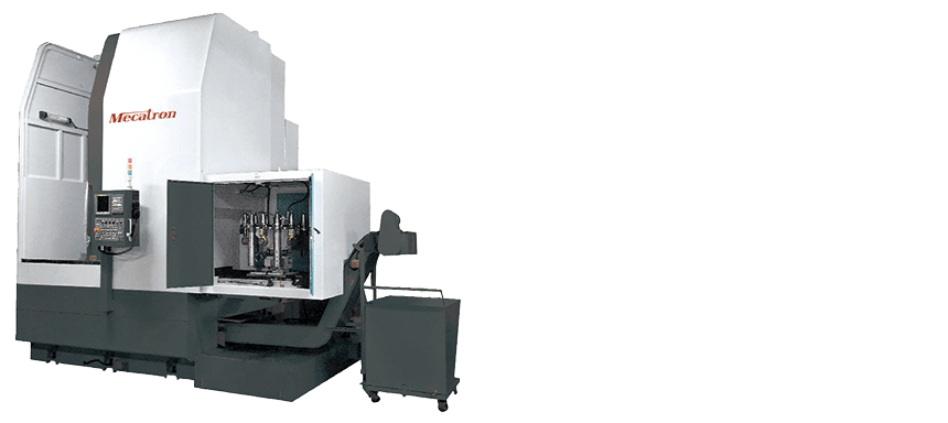
Vertical Turning Lathe
HW-300/450/500/650/800/1000/1100/1200
- FEATURE
- EXPLAIN
- SPECIFICATIONS
- Due to the heavy gravity of the parts, instability may occur. Using a vertical lathe for cutting can help avoid gravity-related instability. Additionally, securing the workpiece with a fixture ensures a perfect contact face on the part’s base, facilitating high-precision manufacturing.
- The machine construction is designed with a box concept, providing maximum stability and rigidity to the machine bed.
- It is especially suited for manufacturing large, thin, and irregularly shaped workpieces.
- The ergonomic design facilitates easy loading and unloading of parts, making it particularly suitable for automatic production lines.
- Its compact design and flexibility make it ideal for assembly line manufacturing systems.
- The independent cooling and chip removal systems are highly efficient for maintenance and service.
- The main spindle is supported by high-precision bearings at the front, middle, and rear, with optimal supporting distances to ensure top-tier precision, superior rigidity, high rotation speed and stable performance.
- Each axis is equipped with high-rigidity precision linear guides and ball screws, integrated with high responsiveness AC servo motors, ensuring high repeatability and suitability for heavy-duty operations.
Linear Guide and Ball Screw
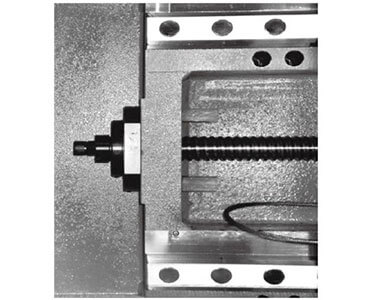
The machine features a wide span with high-accuracy class ball screws and linear guideways. All bearing support positions include Iubrication system to ensure Iong-term precision, stability, and extended machine life.
Nitrogen Gas Balance System
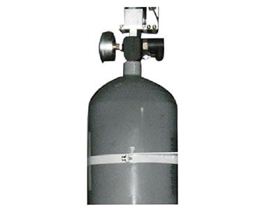
The Z-axis nitrogen balance system enhances turning speed and stability, eliminating counterweight-related vibrations and resulting in a smoother cutting surface.
Hydraulic Chuck Clamping
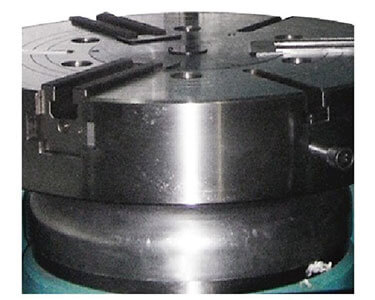
The high-precision design and installation ensure that after the chuck is mounted on the spindle, the spindle rotation accuracy for a diameter of 500 mm can achieve a deflection accuracy of 0.01 mm.
Main Spindle
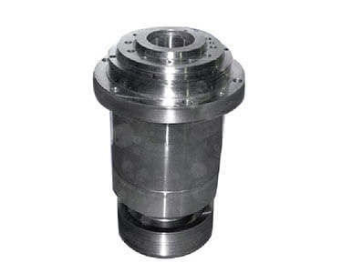
Due to the special design and arrangement of the spindle bearings, the spindle can support maximum vertical
loading. (Values do not include the table and chuck.)
Loading: 4000 kg (HW-800)
Loading: 5800 kg (HW-1000)
Loading: 6500 kg (HW-1200)
Casting Body and Column
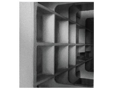
The one-piece casting base provides a heavy and rigid structure.
Finite Element Method (FEM) analysis ensures an optimized structure, minimizing deformation during metal cutting.
Specifications
| MODEL | Unit | HW-300 | HW-450 | ||
|---|---|---|---|---|---|
| WORKING SPACE | Max swinging dia. | mm | 500 | 650 | |
| Max cutting dia. | mm | 350 | 450 | ||
| Max cutting height | mm | 300 | 360 | ||
| Tool to table surface | mm | 320 | 375 | ||
| Spindle nose to table surface | mm | ~ | ~ | ||
| TABLE | Table diameter | inch | 8 | 12 | |
| Max. loading | kg | 360 | 520 | ||
| Max. torque | Nm | 140 | 140 | ||
| Spindle & Bearing Size | A6(100TAC) | A6(100TAC) | |||
| Spindle speed (low) | rpm | ~ | ~ | ||
| Spindle speed (high) | rpm | 50~3000 | 50~3000 | ||
| TURRET | Turret type | Carousel | Carousel | Vertical | |
| Tool number | set | 8 | 8 | 6 | |
| Tool max. loading | kg | 60 | 20 | 20 | |
| Tool change time | sec. | 2 | 2 | 3 | |
| Tool size | mm | □20 Ø40 | □25Ø40 | □25Ø40 | |
| TRAVEL AND FEEDRATE | X-Max travel | mm | -30/210 | -20/255 | -50/255 |
| Z-Max travel | mm | 300 | 360 | 360 | |
| X Rapid feedrate | mm/min | 15000 | 15000 | ||
| Z Rapid feedrate | mm/min | 15000 | 15000 | ||
| MOTOR | X-Axial servo motor | kw | 0.75 | 1.2 | 1.2 |
| Z-Axial servo motor | kw | 1.2 | 1.8 | 1.8 | |
| Spindle motor | kw | 7.5/11 | 11/15 | 11/15 | |
| MACHINE LAYOUT | Machine height | mm | 2080 | 2080 | |
| Machine layout (L*W) | mm | 1820 x1450 | 1990 x1520 | ||
| Machine weight | kg | 3200 | 4900 | 4850 | |
| Power required | kva | 20 | 25 | ||
| MODEL | Unit | HW-500 | HW-650 | |||||
|---|---|---|---|---|---|---|---|---|
| WORKING SPACE | Max swinging dia. | mm | 720 | 750 | ||||
| Max cutting dia. | mm | 500 | 700 | |||||
| Max cutting height | mm | 450 | 700 | |||||
| Tool to table surface | mm | 450 | 700 | |||||
| Spindle nose to table surface | mm | ~ | ~ | |||||
| TABLE | Table diameter | inch | 15 | 15 | ||||
| Max. loading | kg | 650 | 1000 | |||||
| Max. torque | Nm | 500 | 620 | |||||
| Spindle & Bearing Size | A8(130TAC) | A11(160TAC) | ||||||
| Spindle speed (low) | rpm | ~ | ~ | |||||
| Spindle speed (high) | rpm | 50~2500 | 50~2500 | |||||
| TURRET | Turret type | Carousel | Vertical | Live tooling | Carousel | Vertical | Live tooling | |
| Tool number | set | 8 | 6 | 12 | 8 | 6 | 12 | |
| Tool max. loading | kg | 30 | 25 | 30 | 50 | 40 | 50 | |
| Tool change time | sec. | 2 | 3 | 2 | 2 | 3 | 2 | |
| Tool size | mm | □32 Ø50 | □32 Ø50 | □25 Ø40 | □32 Ø50 | □32 Ø50 | □32 Ø50 | |
| TRAVEL AND FEEDRATE | X-Max travel | mm | -20/290 | -50/260 | -20/290 | -30/390 | -50/370 | -30/390 |
| Z-Max travel | mm | 450 | 700 | |||||
| X Rapid feedrate | mm/min | 15000 | 15000 | |||||
| Z Rapid feedrate | mm/min | 15000 | 15000 | |||||
| MOTOR | X-Axial servo motor | kw | 1.6 | 3 | ||||
| Z-Axial servo motor | kw | 3 | 4 | |||||
| Spindle motor | kw | 15/18.5 | 18.5/22 | |||||
| MACHINE LAYOUT | Machine height | mm | 2460 | 2900 | ||||
| Machine layout (L*W) | mm | 2350 x 1600 | 2440 x 1780 | |||||
| Machine weight | kg | 6900 | 6900 | 6900 | 8000 | 8000 | 8000 | |
| Power required | kva | 35 | 40 | |||||
| MODEL | Unit | HW-800 | HW-1000 | |||||
|---|---|---|---|---|---|---|---|---|
| WORKING SPACE | Max swinging dia. | mm | 850 | 1150 | ||||
| Max cutting dia. | mm | 800 | 1000 | |||||
| Max cutting height | mm | 800 | 800 | |||||
| Tool to table surface | mm | 800 | 800 | |||||
| Spindle nose to table surface | mm | ~ | ~ | |||||
| TABLE | Table diameter | inch | 21 | 32 | ||||
| Max. loading | kg | 1200 | 1650 | |||||
| Max. torque | Nm | 620 | 2640 | |||||
| Spindle & Bearing Size | A11(170TAC) | A15(220TAC) | ||||||
| Spindle speed (low) | rpm | ~ | 5~499 | |||||
| Spindle speed (high) | rpm | 50~2000 | 500~1500 | |||||
| TURRET | Turret type | Carousel | Vertical | Live tooling | Carousel | Live tooling | Marehouse | |
| Tool number | set | 8 | 6 | 12 | 8 | 12 | 12 | |
| Tool max. loading | kg | 50 | 40 | 50 | 60 | 60 | 60 | |
| Tool change time | sec. | 2 | 3 | 2 | 2 | 2 | 20 | |
| Tool size | mm | □32 Ø50 | □32 Ø50 | □32 Ø50 | □32 Ø50 | □32 Ø50 | BT50 | |
| TRAVEL AND FEEDRATE | X-Max travel | mm | -35/460 | -75/420 | -35/460 | -60/570 | ||
| Z-Max travel | mm | 850 | 800 | |||||
| X Rapid feedrate | mm/min | 15000 | 12000 | |||||
| Z Rapid feedrate | mm/min | 15000 | 12000 | |||||
| MOTOR | X-Axial servo motor | kw | 3 | 4 | ||||
| Z-Axial servo motor | kw | 4 | 7 | |||||
| Spindle motor | kw | 18.5/22 | 37/45 | |||||
| MACHINE LAYOUT | Machine height | mm | 3135 | 3550 | 3750 | |||
| Machine layout (L*W) | mm | 2680 x 1980 | 3250 x 2400 | |||||
| Machine weight | kg | 10000 | 10000 | 10500 | 13500 | 15200 | ||
| Power required | kva | 40 | 60 | |||||
| MODEL | Unit | HW-1100 | HW-1200 | |||||
|---|---|---|---|---|---|---|---|---|
| WORKING SPACE | Max swinging dia. | mm | 1350 | 1350 | ||||
| Max cutting dia | mm | 1100 | 1200 | |||||
| Max cutting height | mm | 800 | 900 | |||||
| Tool to table surface | mm | 800 | 900 | |||||
| Spindle nose to table surface | mm | ~ | ~ | |||||
| TABLE | Table diameter | inch | 32 | 32 | ||||
| Max. loading | kg | 1900 | 2300 | |||||
| Max. torque | Nm | 2640 | 3300 | |||||
| Spindle & Bearing Size | A15(220TAC) | A15(220TAC) | ||||||
| Spindle speed (low) | rpm | 5~499 | 5~499 | |||||
| Spindle speed (high) | rpm | 500~1000 | 500~800 | |||||
| TURRET | Turret type | Carousel | Live tooling | Marehouse | Carousel | Live tooling | Marehouse | |
| Tool number | set | 8 | 12 | 12 | 8 | 12 | 12 | |
| Tool max. loading | kg | 60 | 60 | 60 | 60 | 60 | 60 | |
| Tool change time | sec. | 2 | 2 | 20 | 2 | 2 | 20 | |
| Tool size | mm | □32 Ø50 | □32 Ø50 | BT50 | □32 Ø50 | □32 Ø50 | BT50 | |
| TRAVEL AND FEEDRATE | X-Max travel | mm | -60/640 | -60/725 | -30/830 | |||
| Z-Max travel | mm | 800 | 900 | |||||
| X Rapid feedrate | mm/min | 12000 | 12000 | |||||
| Z Rapid feedrate | mm/min | 12000 | 12000 | |||||
| MOTOR | X-Axial servo motor | kw | 4 | 7 | ||||
| Z-Axial servo motor | kw | 7 | 7 | |||||
| Spindle moto | kw | 37/45 | 37/45 | |||||
| MACHINE LAYOUT | Machine height | mm | 3550 | 3750 | 3750 | 3860 | ||
| Machine layout (L*W) | mm | 3500 x 2590 | 3550 x2790 | 3550x3520 | ||||
| Machine weight | kg | 15400 | 15800 | 16500 | 19000 | |||
| Power required | kva | 60 | 60 | |||||
