

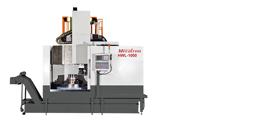
Move Beam / Fixed Beam Vertical Turning Lathe
HWL(F)-1100/1200/1600
- FEATURE
- SPECIFICATIONS
- The machine body design is ergonomic and easy to operate. It is made from high-grade Meehanite cast iron and subjected to tempering heat treatment, guaranteeing long-term performance without deformation. Additionally, it offers high efficiency, rigidity, speed, and stability, making it ideal for metal and mold manufacturing needs.
- The guideways are ground and done by precision scraping. The evenly supported design of the guideway block ensures absolute stability during machining, resulting in optimal precision performance.
- The crossed roller bearings enhance the stability of the worktable while reducing the starting torque.
FIXED BEAM
| DESCRIPTION | Unit | HWLF-1000 | HWLF-1200 | HWLF-1600 | ||||
|---|---|---|---|---|---|---|---|---|
| CAPACITY | Max swinging dia. | mm | 1350 | 1550 | 1850 | |||
| Max cutting dia | mm | 1100 | 1350 | 1750 | ||||
| Max cutting height | mm | 900 | 1000 | 1000 | ||||
| Ram end to table surface | mm | 1200 | 1250 | 1250 | ||||
| TABLE | Table diameter | mm | 1000 | 1250 | 1600 | |||
| Max. loading | ton | 7 | 9 | 10 | ||||
| Max. torque | Nm | 11600 | 13100 | 16900 | ||||
| Table speed (low) | rpm | 3~120 | 3~107 | 3~83 | ||||
| Table speed (high) | rpm | 121~350 | 108~300 | 84~250 | ||||
| ATC | Turret type | set | BT-50 (Gears: OP) | BT-50 (Gears: OP) | BT-50 (Gears: OP) | |||
| Tool number | set | 12 | 16 (C axis) | 12 | 16 ( C axis) | 12 | 16 (C axis) | |
| Tool loading | kg | 50 | 50 | 50 | ||||
| Ram size (H*W) | mm | 200~200 | 220~220 | 220~220 | ||||
| Tool change time | Sec | 30 | 30 | 30 | ||||
| TRAVEL AND FEED | X-axis travel | mm | -200/670 | -200/860 | -200/1150 | |||
| Z-axis travel | mm | 900 | 1000 | 1000 | ||||
| X Rapid feedrate | mm/min | 10000 | 10000 | 10000 | ||||
| Z Rapid feedrate | mm/min | 10000 | 10000 | 10000 | ||||
| MOTOR | X-Axial servo motor | kw | 7 | 7 | 7 | |||
| Z-Axial servo motor | kw | 7 | 7 | 7 | ||||
| Spindle moto | kw | 37/45 | 37/45 | 37/45 | ||||
| C-axis servo motor | kw | ~ | 7 (C axis) | ~ | 7( C axis) | ~ | 7 (C axis) | |
| Tool spindle motor | Kw | ~ | 7.5/11 (C axis) | ~ | 7.5/11 (C axis) | ~ | 11/15 (C axis) | |
| MACHINE LAYOUT | Machine height | mm | 4070 | 4120 | 4350 | |||
| Machine layout (L*W) | mm | 3600 x 5900 | 3750 x 6100 | 3900 x 6350 | ||||
| Machine weight | kg | 21000 | 21400 (C axis) | 24500 | 25000 ( C axis) | 29000 | 29650 ( C axis) | |
| Power required | kva | 60 | 60 | 60 | ||||
MOVE BEAM
| DESCRIPTION | Unit | HWL-1000 | HWL-1200 | HWL-1600 | ||||
|---|---|---|---|---|---|---|---|---|
| CAPACITY | Max swinging dia. | mm | 1350 | 1550 | 1850 | |||
| Max turning diameter | mm | 1100 | 1350 | 1750 | ||||
| Max turning height | mm | 950 | 1300 (optional 1600/1800) | 1300 (optional 1600/1800) | ||||
| Ram end to table surface | mm | 1200 | 1500 | 1250 | ||||
| TABLE | Table diameter | mm | 1000 | 1250 | 1600 | |||
| Max. loading | ton | 7 | 9 | 10 | ||||
| Max. torque | Nm | 11600 | 13100 | 16900 | ||||
| Table speed (low) | rpm | 3~120 | 3~107 | 3~83 | ||||
| Table speed (high) | rpm | 121~350 | 108~300 | 84~250 | ||||
| ATC | Turret type | set | BT-50 (Gears: OP) | BT-50 (Gears: OP) | BT-50 (Gears: OP) | |||
| Tool number | set | 12 | 16 (C axis) | 12 | 16 ( C axis) | 12 | 16 (C axis) | |
| Tool loading | kg | 50 | 50 | 50 | ||||
| Ram size (H*W) | mm | 200~200 | 220~220 | 220~220 | ||||
| Tool change time | Sec | 30 | 30 | 30 | ||||
| TRAVEL AND FEED | X-axis travel | mm | -200/670 | -200/860 | -200/1150 | |||
| Z-axis travel | mm | 900 | 1000 | 1000 | ||||
| X Rapid feedrate | mm/min | 500 | 800 (optional 1200/1400) | 800 (optional 1200/1400) | ||||
| Z Rapid feedrate | mm/min | 10000 | 10000 | 10000 | ||||
| MOTOR | X-Axial servo motor | kw | 7 | 7 | 7 | |||
| Z-Axial servo motor | kw | 7 | 7 | 7 | ||||
| Spindle moto | kw | 37/45 | 37/45 | 37/45 | ||||
| C-axis servo motor | kw | ~ | 7 (C axis) | ~ | 7( C axis) | ~ | 7 (C axis) | |
| Tool spindle motor | Kw | ~ | 7.5/11 (C axis) | ~ | 7.5/11 (C axis) | ~ | 11/15 (C axis) | |
| MACHINE LAYOUT | Machine height | mm | 4700 | 5000 | 5100 | |||
| Machine layout (L*W) | mm | 3600 x 5900 | 3750 x 6100 | 3900 x 6350 | ||||
| Machine weight | kg | 21000 | 21400 (C axis) | 24500 | 25000( C axis) | 29000 | 29650( C axis) | |
| Power required | kva | 60 | 60 | 60 | ||||
